
IMPORTANT NOTE: I included informational details in both folder names and file names, but on some computer systems, those long names prevent the files from being opened! If this affects you, then once you’ve made note of the info details, shorten all the folder names and file names. All the files open for me!
Views, info, and downloads for parametric CNC Table with Wood Side Rails and option with Metal Strut Side Rails:
Clickable links for content on this page:
-
- LR3 Gantry Placement, X-Axis Tube Length, re. MDF for cuttable area
- Table with Wood Side Rails
- Table with Metal Strut Side Rails
- Notes on both table versions (wood and metal rails)
- Benefits
- Online Preview Links (Fusion 360 viewer)
- Editable F360 archive file downloads
- DXF cut plans
- How to “bootstrap” cut this table even before you have a table (assuming you’ve already built your LowRider v3)
- Questions and Answers
LR3 gantry placement, X-axis Tube length, etc. re. MDF for cuttable area
Please check out the helpful build info posted by @steved on the V1E forum here: https://forum.v1e.com/t/bootstrapping-design8studio-table/39908/
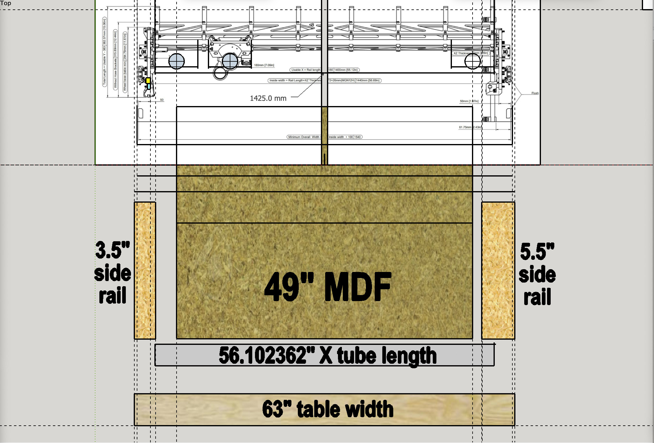
THE IMAGE BELOW IS FOR TABLES WITH WOOD SIDE RAILS
(see below for image for metal strut side rails)
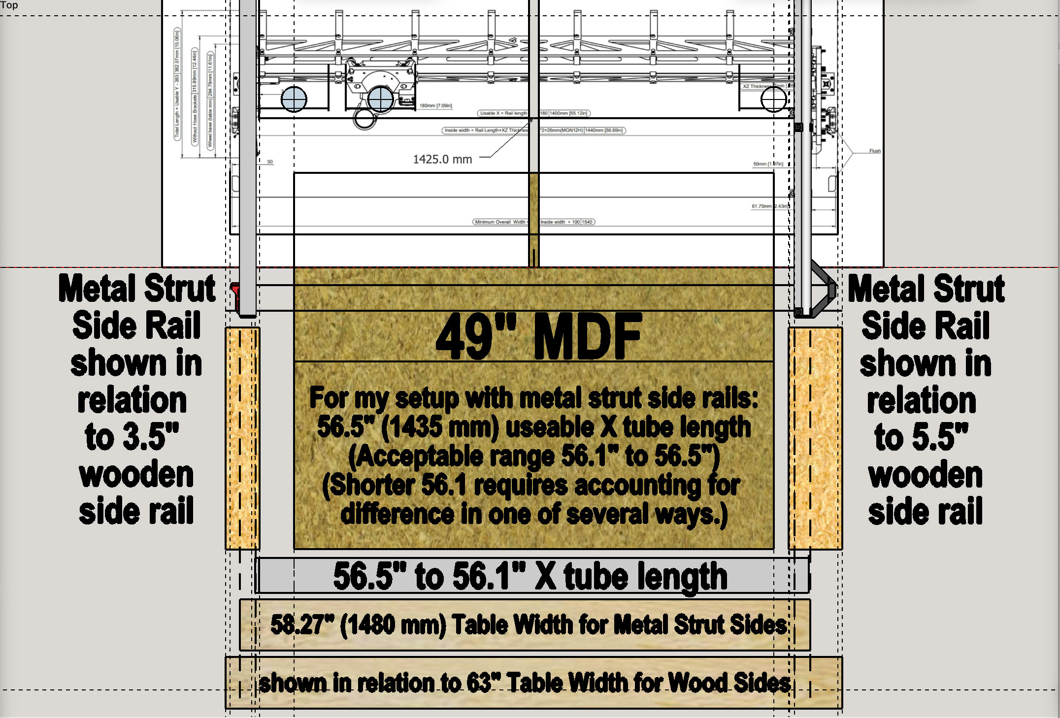
(see above for image for wood side rails)
I’ve used both the LR3 calculator and some visual reinforcement based on the illustration of LR3 dimensions (from the V1E docs), which I slightly modified for a 49″ cut width (for MDF that’s 49 x 97). Above is an illustration of what this table is designed for, in general, as something that can accommodate both printed XZ plates (which are a bit thicker) as well as thinner XZ plates that were cut from metal (typically 1/4″ thick).
TUBE LENGTH for X-gantry – FOR TABLES WITH WOOD SIDES:
In its default setup, this design is made for a tube length (X axis) of 56.102362″ (1425 mm). Please note that in the user parameters of the Fusion 360 file, there is a param that auto calculates this. If you should need to alter the width of the design, you can consult the updated value of that parameter to get the new tube length.
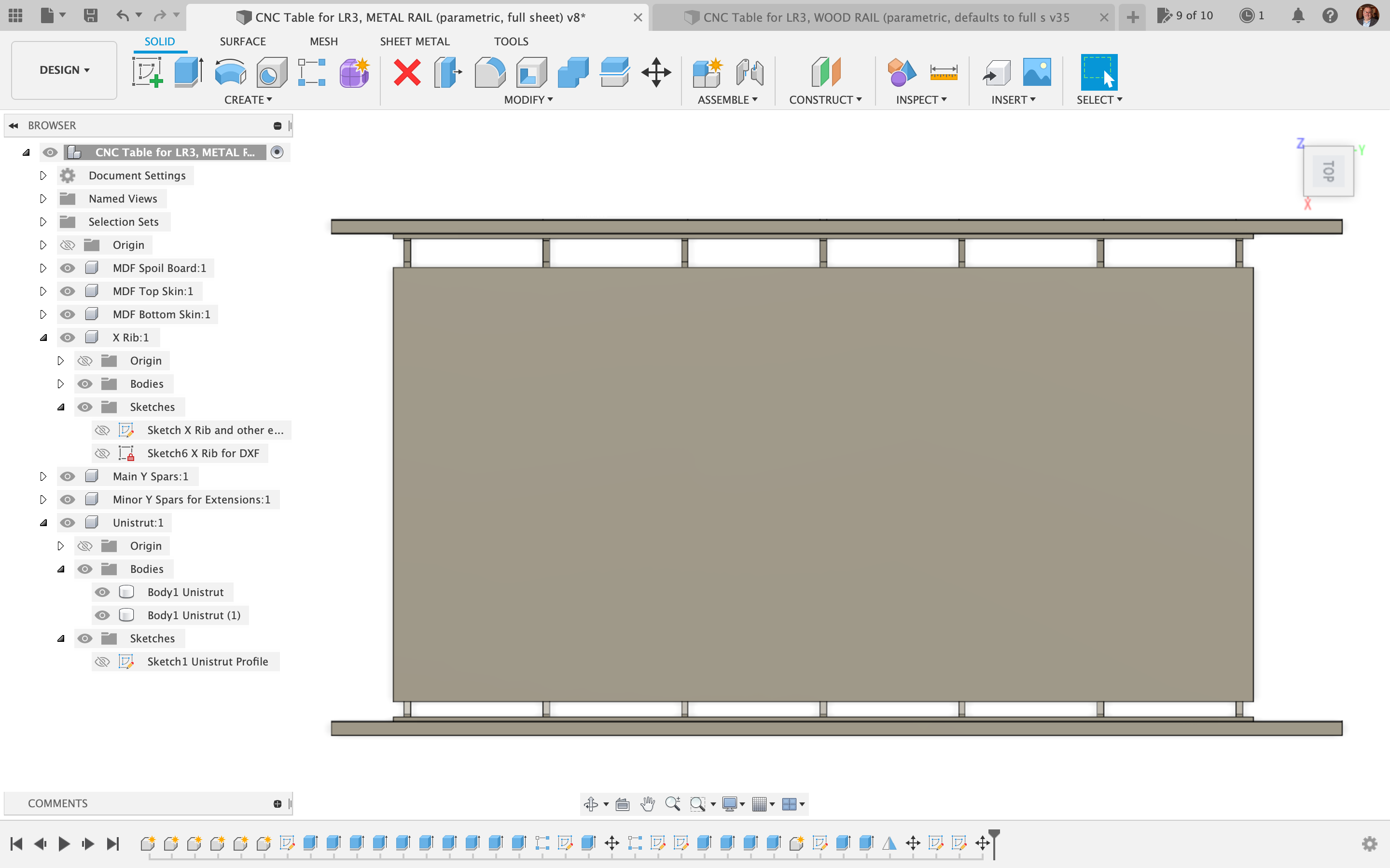
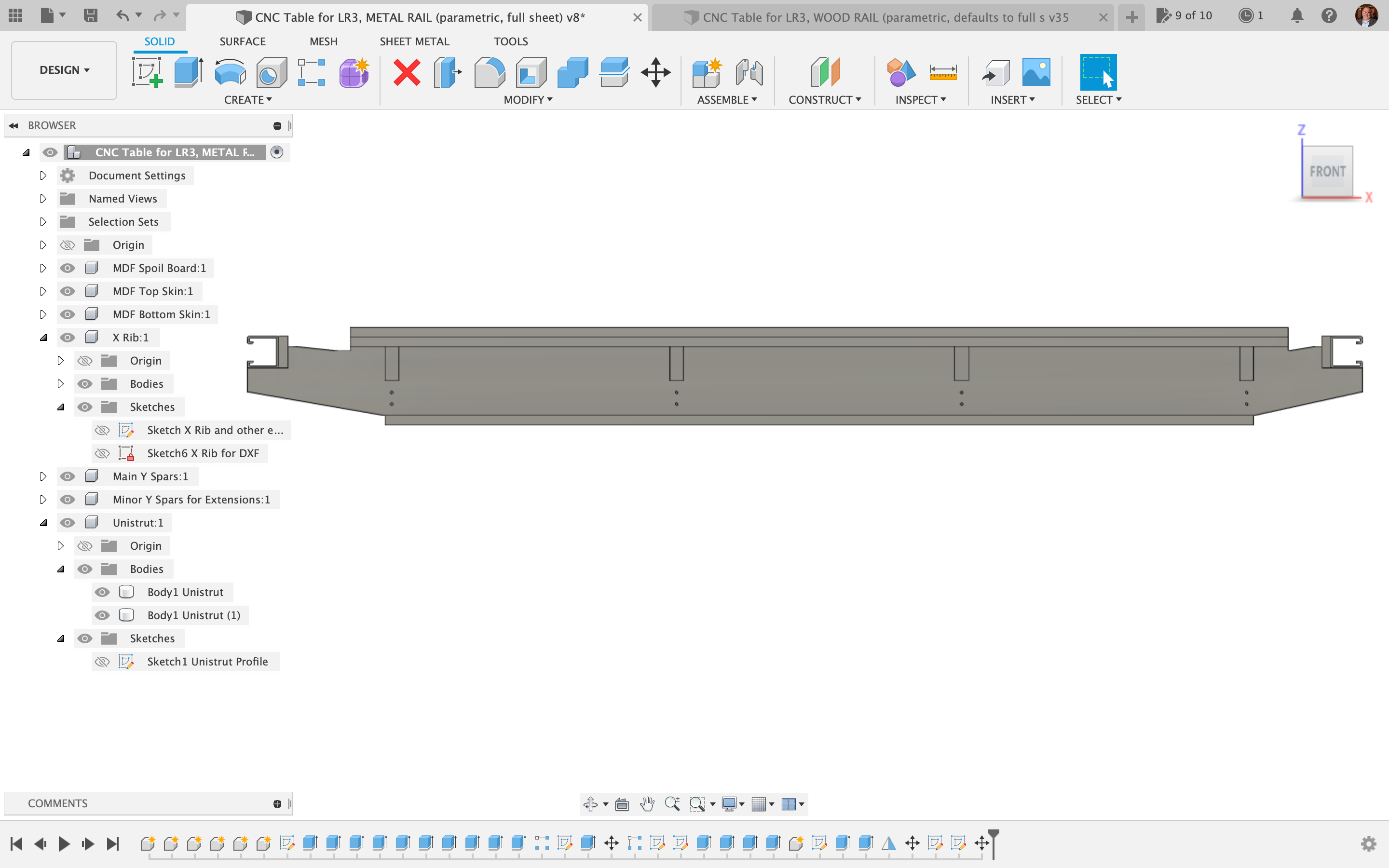
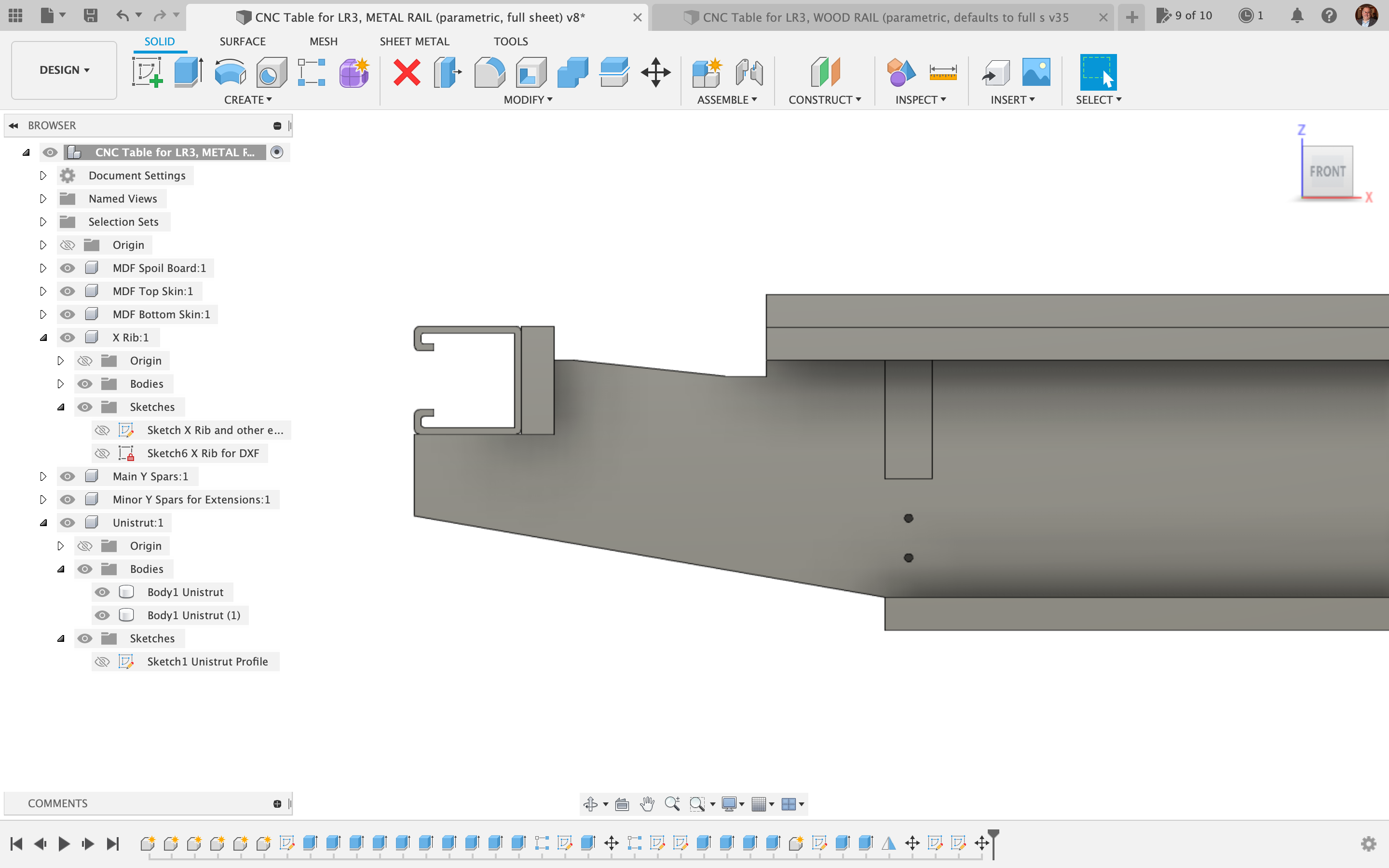
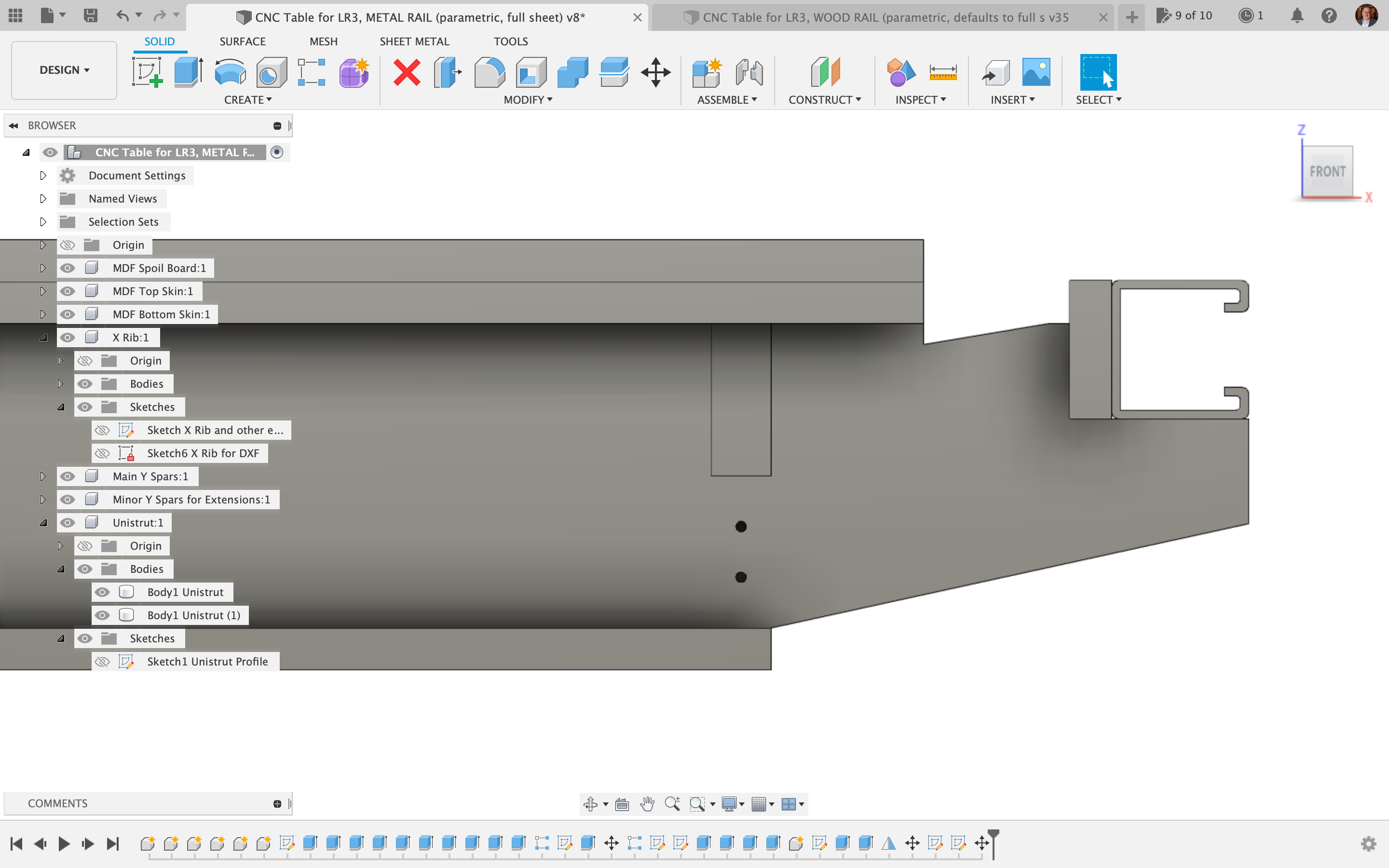
Based on my efforts to comply with the design constraints and dimensions, the 2D illustration below shows what the X-rib profile should look like, with MDF sheets shown for bottom skin, top skin, spoil board, and some type of wood material for the side rail riding plates and vertical supports for them.
TUBE LENGTH for X-gantry – FOR TABLES WITH METAL STRUT SIDES:
The suggested range of X-axis width, 1425 – 1435 mm (i.e. 56.1 to 56.5″, or more precisely, 56.102362″ to 56.49606″) allows for:
-
- Option of having the normal “belt above the table” approach, with the bearing wheels (on the non-rail side) riding more centered on the metal strut, or
- Option having my “belt (on non-rail side) hidden inside the metal strut” approach, with the bearing wheels (on the non-rail side) riding closer to the edge of the metal strut.
The following helpful documentation was written and posted by @steved, on the V1E forum:
Note: The table cuts and build remain the same for all of the following X-gantry lengths.
EMT TUBE LENGTH for X-gantry – FOR TABLES WITH METAL STRUT SIDES:
Note: Testing has not been performed for use with Optional Urethane Wheels.
If you already have an X-gantry size other than listed, you can cut your strut plates to your choice of size as listed below. You would then need to buy new EMT/tubing and cut to match your choice.
All of the gantry sizes listed below will work with the LR3 adjustable table extenders published on Printables (September 19, 2023).
A. 1425 mm (56.1″) X-gantry length, based on using LR3 non-adjustable table extenders (wood or printed)
B. 1435 mm (56.5″) X-gantry length, based on using LR3 HIDE/PROTECT non-rail side Y AXIS BELTS inside metal strut. This option brings the non-rail side Y Bearing Wheel Bracket closer to the edge of the metal strut to aid in the installation of the mod.
C. 1400 mm (55.1″) X-gantry length, based on using LR3 table extenders (wood or printed, or adjustable). This option works by not installing the two MDF 1/2″-thick spacers before installing the metal strut as per plans. This allows LowRider makers who are building this table and already have a full standard LR3 full sheet build to quickly move to the new table. To use the full area of the design, installing option A or B and the two 1/2″ spacers can be done at a later time.
Thanks, Steve, for the helpful info!
In the “user parameters” of the Fusion 360 file, there is a parameter that auto calculates the X-tube length based on your set cuttable width, etc. If you should need to alter the width of the design by editing parameter(s), you can consult the updated value of that parameter to get the new tube length. That X-tube length parameter corresponds to the default setup, in which the design is made for a tube length (X axis) of 56.49606″ (1435 mm), but if you want to use some other length, such as 56.102362″ (1425 mm), you can still be fine. It just means that amount (0.4″ in this case) will need accommodated for in one of several ways, which can simply be use of normal belt setup instead of the hidden belt setup.
Based on my efforts to comply with the design constraints and dimensions, the 2D illustration below shows what the X-rib profile should look like, with MDF sheets shown for bottom skin, top skin, spoil board, and some type of wood material for the side rail riding plates and vertical supports for them.
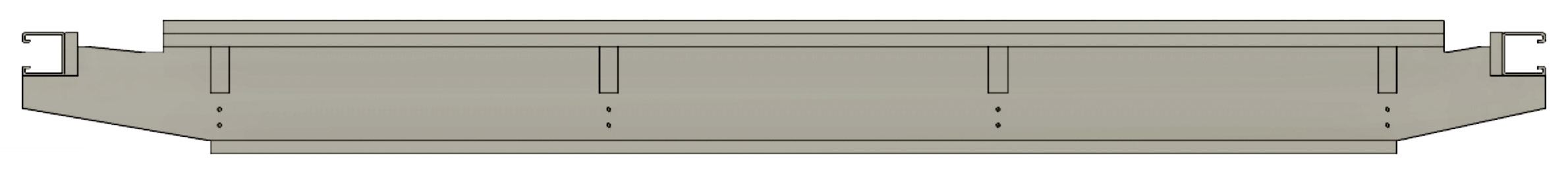
Table with Wood Side Rails
Calls for either five (5) 49″ x 97″ sheets of MDF ( one 3/4″ thick and four 1/2″ thick), or one (1) 4’x’8 sheet of 3/4″ plywood, and another four (4) 49″ x 97″ sheets of 1/2″ MDF. The 3/4″ thick sheet is for making the torsion box, and the four 1/2″ thick sheets are for side rails (for “riding plates”), plus bottom skin, top skin, and sacrificial spoil board top layer.
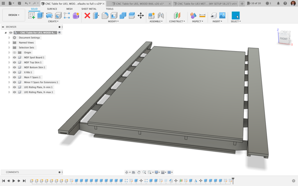
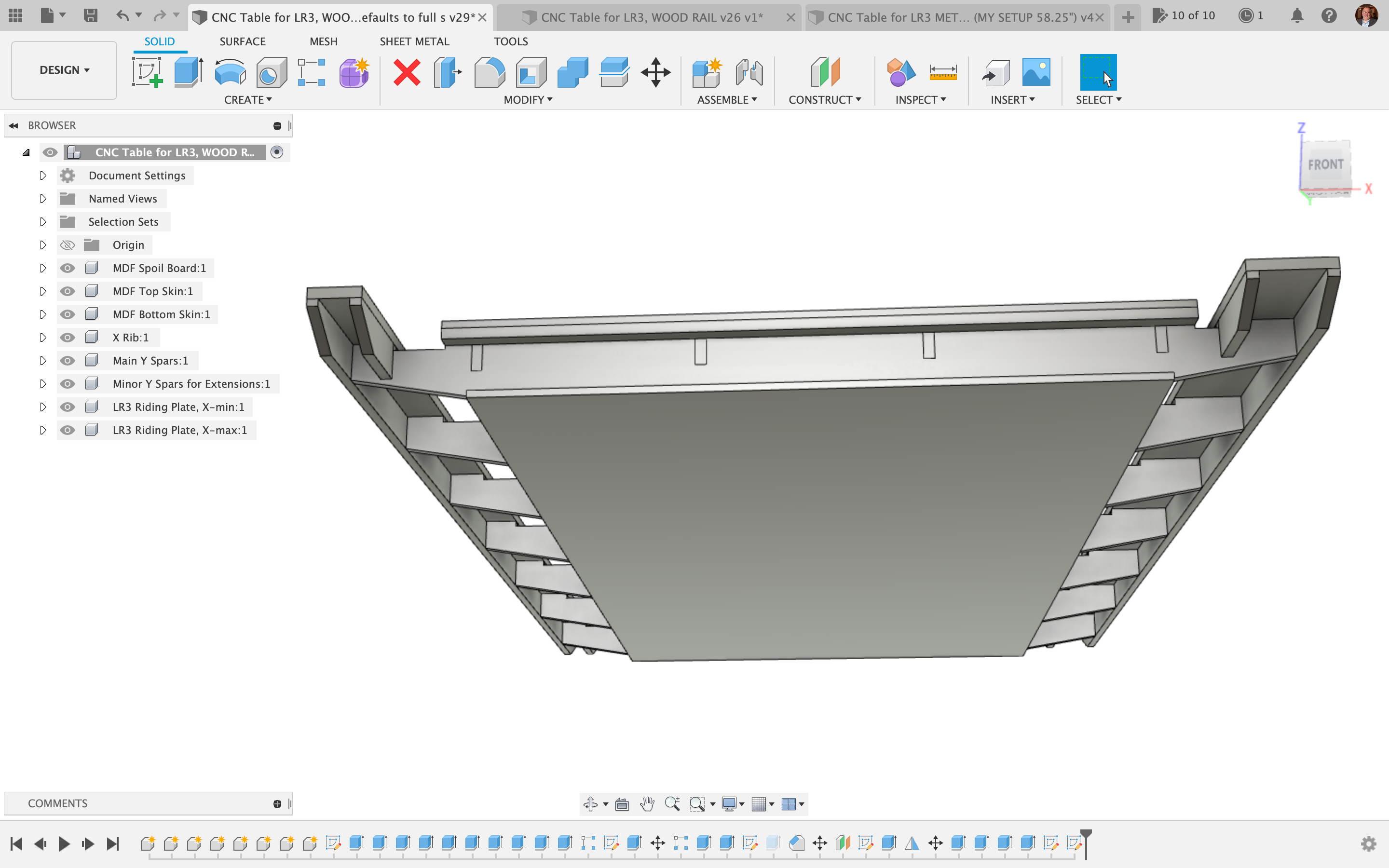
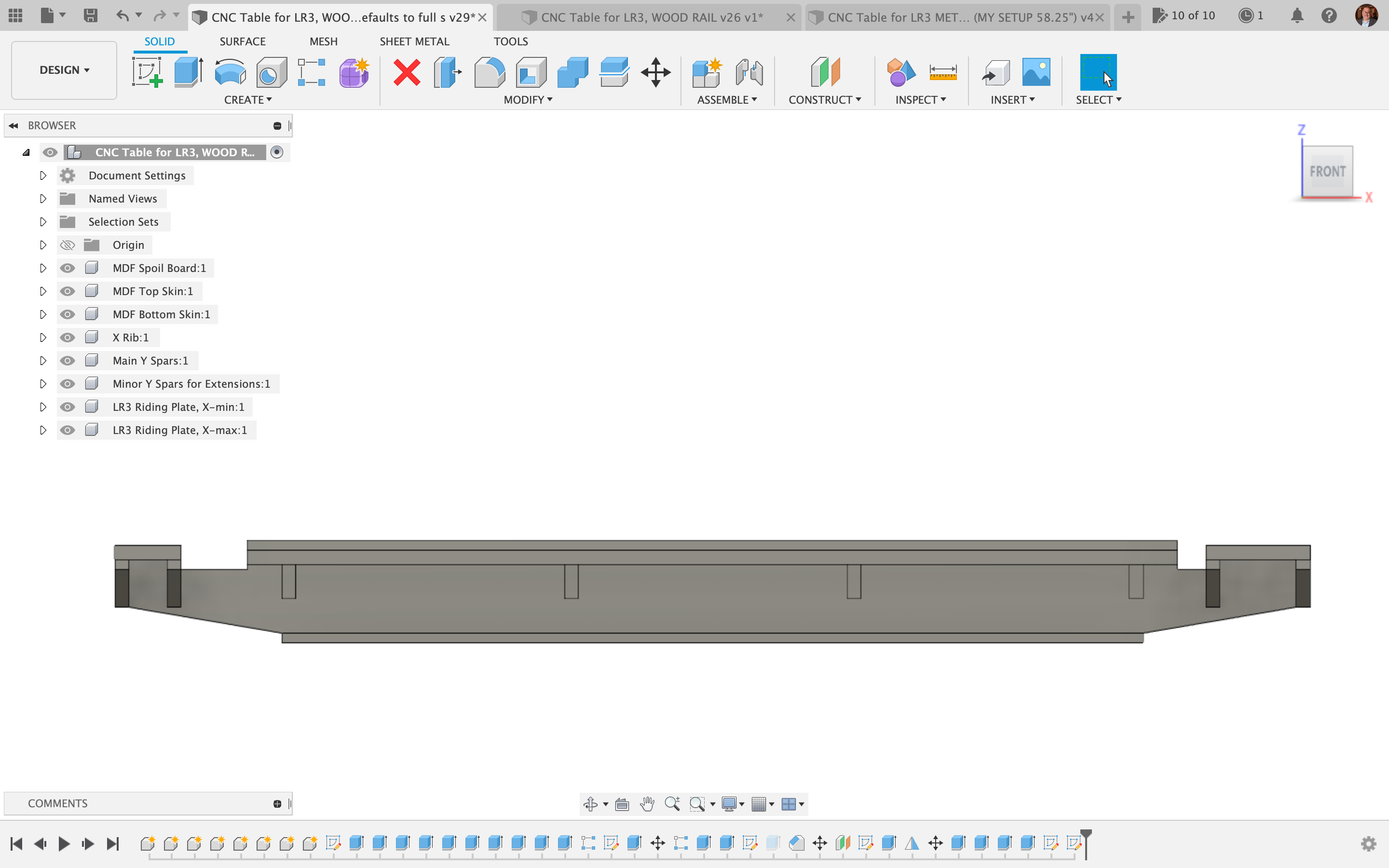
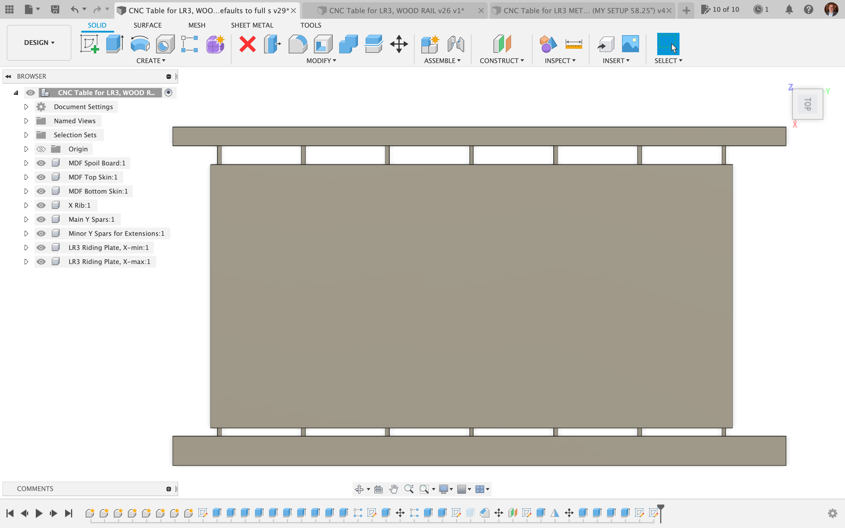
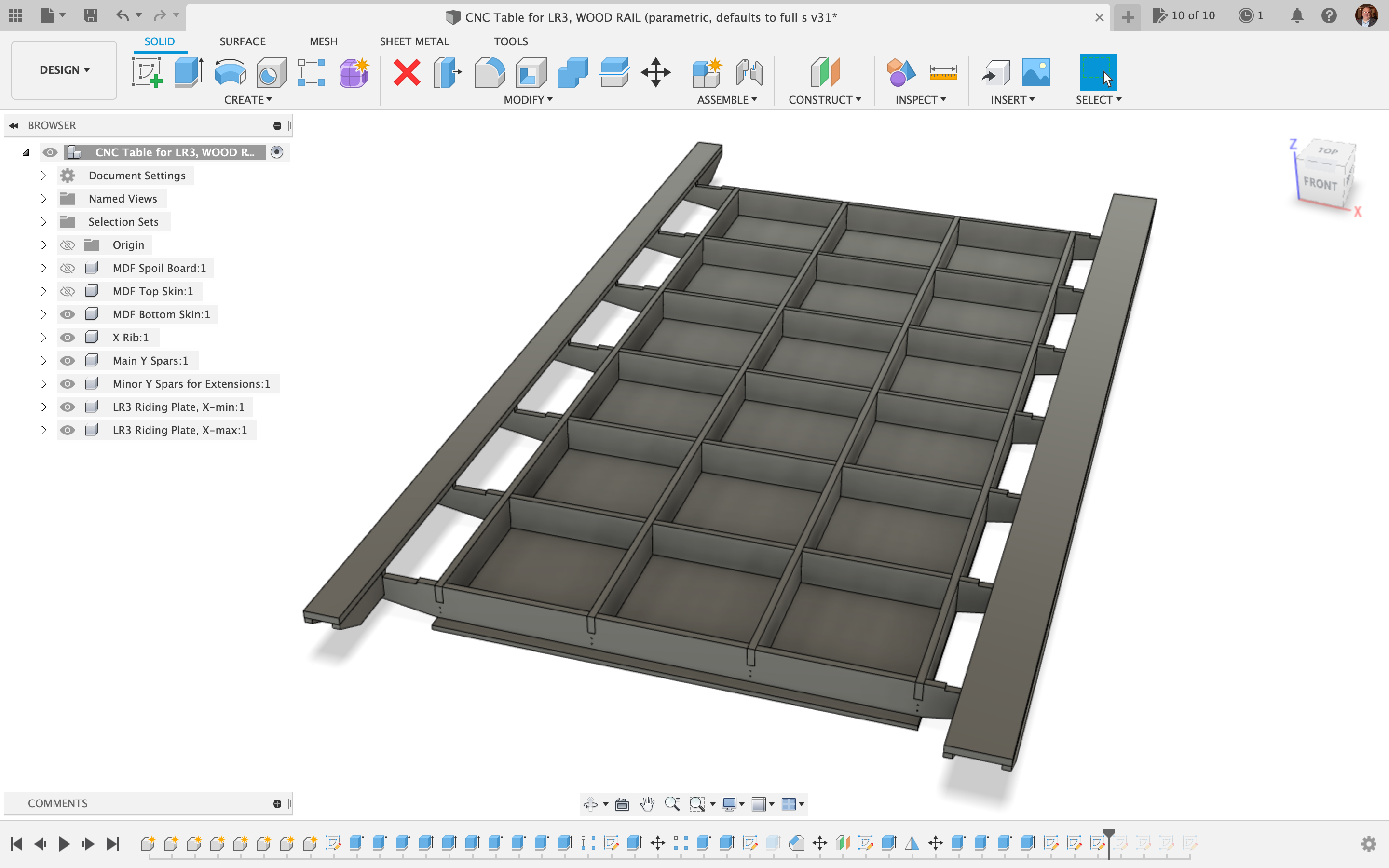
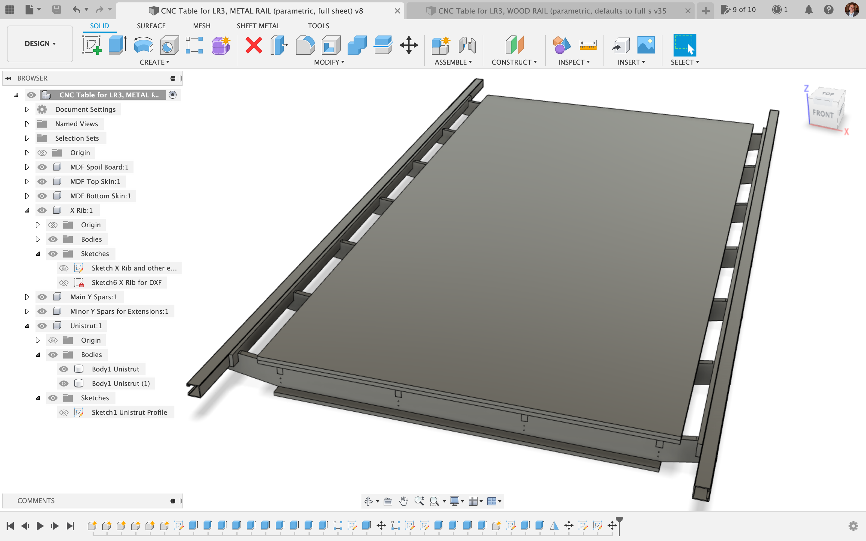
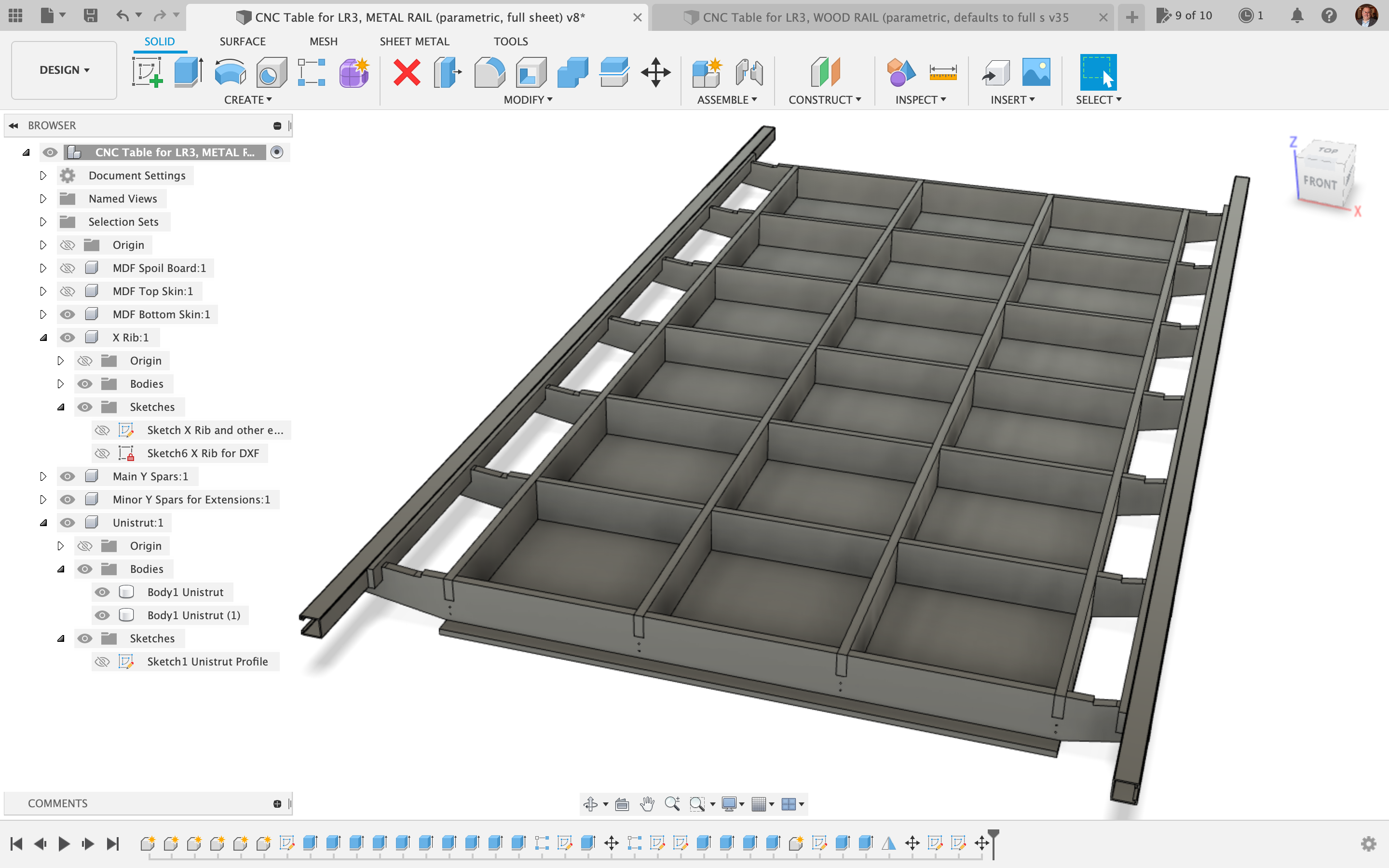
Table with Metal Strut Side Rails (aka Unistrut, aka Superstrut)
NEW as of June 25, 2024: Fellow V1 maker and YouTube member @clayscustom requested a version of the metal rails table that is 6 inch tall. I created this file for him. Please note: a key difference between the cut plan DXF and the Fusion 360 file, is this DXF cut plan was modified so the resulting table will not need the strips of wood mounted behind the super struts. The super struts would be screwed straight to the X ribs of the torsion box. The change was not made in the Fusion file. Click here for the Zip file that has both Fusion, DXF’s, and a CorelDRAW file used for editing the vectors for the cut plan. This design calls for about 1.5 sheets of plywood or MDF that’s 23/32 inches thick. THE INFO BELOW IS OLD, EARLIER INFO.
Calls for one (1) 4’x’8 sheet of 3/4″ plywood or MDF to make the torsion box, and three (3) 49″ x 97″ sheets of 1/2″ MDF for bottom skin, top skin, and sacrifice spoil board top layer.
Notes on both table versions (wood and metal strut rails)
As of April 13, 2023, I have completed Fusion 360 editable parametric files for both a CNC table with wood side rails and a CNC table with metal strut side rails. Also, I have completed a pre-arranged cut plan (in inches, not metric) for both the wood side rails version and the metal strut side rails version.
IMPORTANT: When assembling, pay close attention to the orientation of the X-ribs, because on both designs, the X-min side is different from the X-max side. Make sure the ribs are turned the right way, so all the X-min sides are together, and all the X-max sides are together. You may want to mark them or label them after cutting and before moving them, so you can easily tell which side is which. You can thank me later!
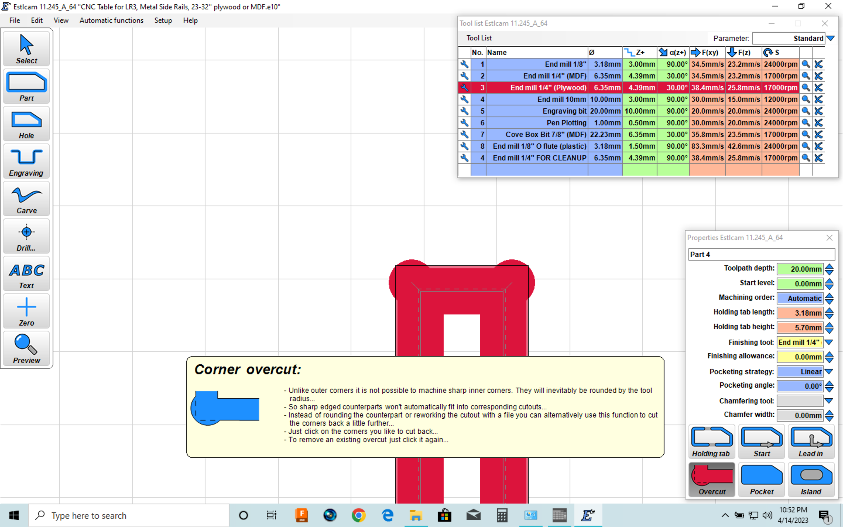
IMPORTANT: When setting up your cut job (regardless of whether in ESTLcam or some other CAM software) it is crucial to use the “Overcut” feature on all inside corners that will have another piece of wood fitting into the opening. This feature is also called “dog bones” because of how the result looks. If you don’t do this, your torsion box WILL NOT fit together without a lot of work chiseling and sanding! Below is a screen shot that not only shows me using this feature in ESTLcam, but also showing my tool settings for a 1/4″ end mill cutting plywood, including speeds, feeds, and RPMs. For reference, 17,000 RPM on a Makita 700 series router is done by setting the dial on “3.” If you are using a 1/8″ end mill, the RPMs should be about 24,000 RPM, which on a Makita 700 series router is done by setting the dial on about “4.5.”
IMPORTANT: This is all based on a common sheet good thickness of 23/32″ for the torsion box, and that can be cut from a single sheet of 4’x8′ plywood / MDF.
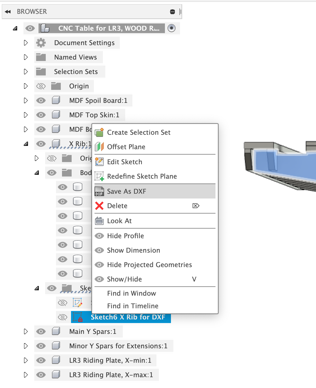
Please measure your plywood / MDF, and if it is different from 0.719” (18.2562 mm) thickness, then you will need to download the Fusion 360 file, edit the user parameters, and change the value of the parameter named Slot_Width. Then in each component, right-click on the sketch identified as “for DXF” in the name, and choose “Save as DXF” to export it. The only two components affected by this are the “X Ribs” and “Main Y Spars” (which together make the main body of the torsion box).
For the metal rails version, only one 4’x8′ sheet is needed for the torsion box, with off-cut strips from the MDF “bottom skin” serving as side rail supports for the metal struts.
NOTE: for the metal strut rails version, you can download and use my printable table extenders that insert into metal struts to provide endstop/tensioner support. The link is: https://www.printables.com/model/220187-lowrider-3-cnc-table-extenders-to-use-lr2-table-wi
For the wood rails version, the cut plan also includes a second 4’x8′ sheet (of which only half is needed, so the unused part can be saved for some other project) which handles all the “long” items for the “riding plates” and the side supports for them. Any reasonable thickness of a 4’x8′ sheet material may be used for these cuts. These are set up for cutting each long part as 3 pieces that can then be glued together.
As of this current set, other thicknesses of plywood / MDF can be handled by either downloading and editing the Fusion 360 file (edit the user parameters and change the value of the third parameter, named Thickness_Plywood_Material) or make a request to me to edit and generate a new cut plan.
Note: My design plan calls for a 1/2″ thick MDF “top skin” on the torsion box, which is considered “permanent,” and then a sacrificial 1/2″ thick MDF spoil board on top of that. If you only re-surface the sacrifice layer, then the torsion box itself only has to endure maybe screw holes from attaching things, and should not need much attention when time comes to replace the spoil board. If this plan is not your cup of tea, you can edit the X Rib sketch and the resulting solid body to change the wing heights as needed.
Inspired by Ryan’s 3D “napkin sketch” illustration of a CNC-cut table for LR3…
Benefits
-
-
- Affordable, requiring only one (1) 4’x8′ sheet of 3/4″ plywood / MDF for the torsion box, and for the “riding plates” (also referred to as “side rails”) either a second 4’x8′ sheet, 1/2″ thick (of either MDF / OSB / particle board / plywood), or two (2) 10′ metal struts (aka “superstrut,” aka “unistrut”). As of April 2023, my material cost locally for the 3/4″ plywood + 2 unistruts approach is $140 (not including the 1/2″ MDF sheets for bottom skin, top skin, and sacrificial spoil board layer, or screws, bolts, etc).
- Incredibly strong torsion box design, helps make the task of getting a decently flat table more within reach.
- Can be “bootstrapped” for new LowRider v3 makers who don’t yet have a table, through making a temporary cut surface by laying a spoil board “stack” on the flattest floor you have available, flanked by some boards for the LR3 to ride on, clamped to the spoil board stack.
- CNC cutting of the X ribs and Y spars helps ensure proper dimensions, ease of assembly, greater stability, and best shot at flatness.
- Compatible with my mod to protect/hide one of the long side belts. If you choose the option for metal strut side rails, my mod is ready to implement. If you choose the wooden side rails option, some remixing would be required.
-
Online Preview Links
Editable F360 archive file downloads
for LR3 TABLE WITH WOOD SIDE RAILS:
-
-
- Wood Side Rails, 21/32’’ plywood (Slot_Width 0.65625’’ or 16.66875mm) 3 5/8’’ tall
- Wood Side Rails, 23/32’’ plywood (Slot_Width 0.719’’ or 18.2562mm) 3 5/8’’ tall
- Wood Side Rails, ~.75’’ plywood (specifically Slot_Width 19.15mm, or 0.75393701’‘) 3 5/8’’ tall
-
for LR3 TABLE WITH METAL STRUT SIDE RAILS:
-
-
- Metal Strut Side Rails, 21/32’’ plywood (Slot_Width 0.65625’’ or 16.66875mm) 3 5/8’’ tall
- Metal Strut Rails, 23/32’’ plywood (Slot_Width 0.719’’ or 18.2562mm) 3 5/8’’ tall
- Metal Strut Rails, ~.75’’ plywood (specifically Slot_Width 19.15mm, or 0.75393701’‘) 3 5/8’’ tall
-
DXF cut plans
for TABLE WITH WOOD SIDE RAILS:
-
-
- LR3 Table, Wood Side Rails, 21/32’’ plywood (Slot_Width 0.65625’’ or 16.66875mm) 3 5/8’’ tall
- LR3 Table, Wood Side Rails, 23:32” plywood (Slot_Width 0.719” or 18.2562mm) CUT PLAN
- LR3 Table, Wood Side Rails, ~.75’’ plywood (specifically Slot_Width 19.15mm, or 0.75393701’‘) 3 5/8’’ tall
-
DXFs for TABLE WITH METAL STRUT SIDE RAILS:
-
-
- LR3 Table, Metal Strut Side Rails, 21/32’’ plywood (Slot_Width 0.65625’’ or 16.66875mm) 3 5/8’’ tall
- LR3 Table, Metal Strut Rails, 23/32’’ plywood (Slot_Width 0.719’’ or 18.2562mm) 3 5/8’’ tall
- LR3 Table, Metal Strut Rails, ~.75’’ plywood (specifically Slot_Width 19.15mm, or 0.75393701’‘) 3 5/8’’ tall
-
How to “bootstrap” cut this table even before you have a table (assuming you’ve already built your LowRider v3)
One approach is to have the three full sheets of 1/2” MDF (which are planned to be the bottom skin, the top skin, and the spoil board) and lay two sheets down on the flattest floor you have, side by side (making an 8’ x 8’ square), and then place the third sheet onto those, placed in the middle, screw it down, and lay some long strips beside the topmost MDF sheet (for to serve as riding plates for the LR3 to ride on). Screw the strips to the MDF sheets underneath them. Attach your LR3 “Y rail” and belt tensioners. Boom. Cut your torsion box!
(For the riding plates — you could cut shorter strips and screw them in an arrangement to form longer strips.)
Questions and Answers
Q: Can I start with the Wood Rails version of the table and later switch to use of Metal Strut Rails?
A: Yes, but… see below for considerations.
A better way to state this question is: can X-Ribs that were originally cut for the Wood Rails version of the table be converted, after the fact, for use with Metal Strut rails instead? The short answer is yes. But bear in mind: the ribs will need some cuts made on them, and the challenge is to reproduce the cuts with precision on each one. A key question will be: are you disassembling the torsion box to make these cuts? If so, making the cuts with precision becomes easier. However, disassembly will only be easily doable if you did not glue your torsion box parts.
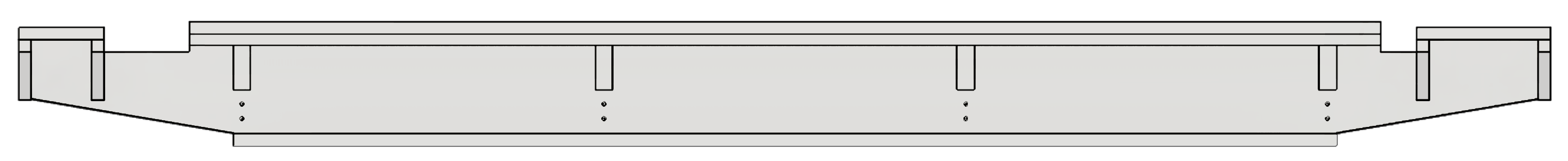
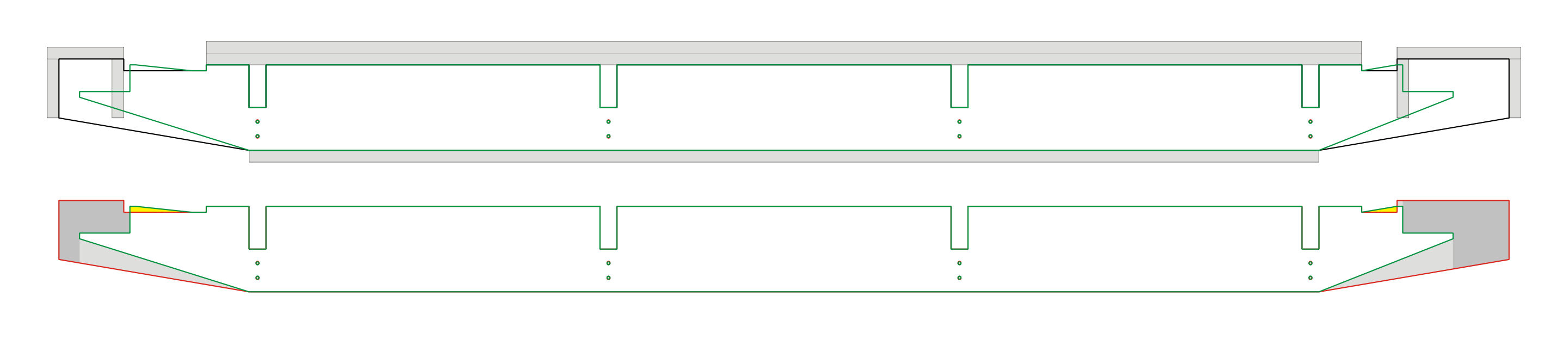
In the illustration below,
-
- The green outlines are X-Ribs for using metal struts, superimposed on the red outlines of X-Ribs for using wood side rails.
- On the lower set, the light gray areas show the cuttable difference between the two.
- On the lower set, the medium gray areas show the minimal cut difference to achieve the transformation.
- On the lower set, the yellow areas show portions that are already gone and yet are OK to do without.
Honestly, I don’t recommend this type of switch. Also, Ryan has indicated that getting long wood side rails that are usable and serve well is not hard to do by cutting multiple pieces (from a full sheet that’s not long enough for single piece cuts) and gluing the shorter pieces together. The ready-to-cut DXF cut plan that I provide above is based on this approach. If you do the wood rails approach and get a usable table, then you are likely to not ever need or want the metal struts version.
On the other hand, if you are wanting to implement my modification that hides and protects the long belt on one side (hiding it inside a metal strut) you may consider either going with the metal rails version from the start, or making this transformation mentioned above, after the fact.
If you find yourself needing to make this transformation from wood rails to metal strut rails, you can click here to download a DXF file of the above illustration, which may help you in measuring for the needed cuts.